
Quality Checklist Forms
| ITSFM Home | New Users & Agencies | Standards | New Construction | Operations & Maintenance | Training |
| Contractor & Consultants | Construction, Engineering & Inspections |
| Roles & Responsibilities | Quality Assurance & Quality Control | As-Built Guidelines | As-Built Document Acceptance Testing |
| Nonconformance Procedure | Nonconformance Reports | Nonconformance Closure Report | Nonconformance Tracking | Quality Checklist Forms |
ITS construction projects are comprised of many specialized system components requiring the CEI to be knowledgeable in a variety of construction disciplines and processes. The quality of construction and system installations has a tremendous impact on the operational effectiveness and the reoccurring maintenance cost associated with ITS subsystems. ITS-specific Quality Checklist forms support the CEI with monitoring the quality of construction. The checklists address several types of ITS facilities and different construction methods used to deploy them.
The following quality checklist forms must be updated to include your project specific installation requirements.

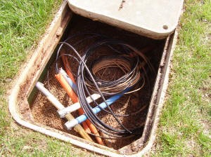
ITS Conduit Access Points consist of Splice Vaults and Pull Boxes. They are utilized to provide access to the conduit system for the installation, operation and maintenance of fiber optic and electrical cables. Splice Vaults are used along the primary or backbone ITS conduit system housing fiber optic cables and pull boxes are used when conduit extends from the backbone conduit system to the ITS field device location. Two types of pull boxes and are typically used, electrical and fiber optic. The electrical and fiber optic conduit may be installed in the same trench or conduit bundle, but the access points for the two, electrical and communication, should be separate.
|  |
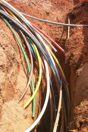
The ITS Conduit System consists of several different types and configurations of conduit and pipes to form the infrastructure that provides the pathway necessary to install, operate and maintain fiber optic and electrical cables between Regional Traffic Management Centers (RTMCs) and the ITS devices. Several construction methods are typically used to install the conduit system including bridge attachment, directional bore, horizontal bore, plow, trench, and existing utility separation methods.
|  |
The Conduit Designating System provides visual notification of the presence of the underground ITS conduit/cable system, as well as provides a means for electronically locating the dielectric conduit system. The Designating System consists of several components, including electronic markers, route markers, above-ground and underground tone wire access points, underground tone wires, wire grounding units (WGU), and ground rods. The Designating System provides a means to identify, locate, and protect the ITS conduit system.
|  |
ITS device placement is critical for effective performance and the delivery of real-time data and video to a central location for analysis and dissemination to affected parties for traffic and incident management. Dynamic Message Signs (DMS) need to be installed so that messages can be safely and effectively viewed by motorists to allow for proper motorist reaction. Radar Detection Systems (RDS) are positioned along the highway to monitor traffic, but need to be strategically located to minimize background interference that may cause less than optimal RDS operation. Closed-Circuit Television (CCTV) cameras are located for optimal views of the highway avoiding trees, buildings and other obstacles that would obscure view. Portable Highway Advisory Radios (HAR) are located along the highway to advise motorists of traffic conditions or broadcast public safety announcements. The device location should be away from any source of radio frequency interference (RFI). Their optimal elevation should be level to, or above, the roadway and not obscured by hills, trees, or other large obstacles to maximize operational range. Portable Variable Message Signs (PVMS) should be located with similar considerations as with the DMS, but offer the flexibility in that they can serve a particular area and then quickly be removed and re-deployed to another location.
|   |
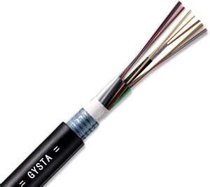
Fiber Optic Cable provides ample bandwidth for all ITS applications including video. It is reliable, a proven technology and cost effective, making fiber optic cable the best media for ITS systems. The cable is comprised of optical fibers that are concentric cylinders made of dielectric materials (i.e., nonmetallic materials that do not conduct electricity). At the center is a core comprised of glass or plastic strand or fiber in which light waves travel. In most ITS applications, optical fiber media requires that electrical signals be converted into light signals for transmission. Light emitting diodes (LED) and light amplification by stimulated emission or radiation (laser) devices are two examples of the technologies used with fiber optic cables.
|   |
ITS Electrical Power Systems differ from other ITS elements in several distinct ways. For instance, power is a non-passive component in the system. If not properly installed, it can endanger personnel and damage ITS equipment. Another differentiator involves the coordination of third-party utility companies to obtain and manage electrical service. As a result, logistics become more complicated when jointly establishing demarcation points for load centers. The ITS Power System utilizes several components designed to minimize danger to personnel and devices, and efficiently distribute power to ITS devices downstream from the electrical service point. Some of these devices limit the flow of current, such as surge protectors, breakers, and grounding devices. Others transmit and distribute power such as cables, load centers, and transformers. It is imperative that the power components of the ITS are installed properly and conform to designed specifications.
|  |
ITS Support Structures for devices and subsystems vary based on need and applicability. Typically, ITS subsystem components are installed on their own structure, which includes poles of varying materials or sign structures that are either cantilever or overhead truss. They are usually a structural steel configuration located within the highway right-of-way (ROW). Moreover, some subsystems are trailer mounted and can be quickly deployed to strategic locations to maximize operational effectiveness. Example types are the PHAR and the PVMS. The process of receiving and transmitting data, resulting in the ability to monitor and alert vehicular or pedestrian traffic, requires a variety of ITS devices ranging from cameras, to DMSs, to wireless antennas. These devices must be readily visible to their target users or their purpose is defeated. That generally requires the devices be mounted in overhead locations requiring ancillary support structures. These support structures are installed in locations to maximize the effectiveness of the devices mounted to them. Typically, ITS support structures are installed in close proximity to moving traffic. To guard public safety, it is critical that special attention is focused on monitoring the installation process to ensure its designed structural integrity is met.
|   |
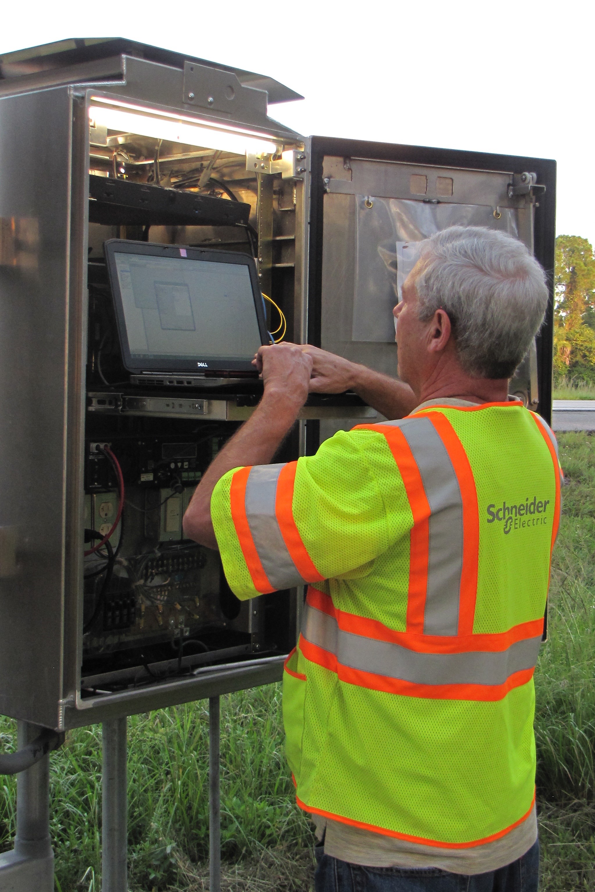
During the construction phase, it is essential to maintain thorough subsystem cabinet inspection in order to ensure dependable subsystem operation. Depending on the type of subsystem served, the cabinet will likely house sensitive micro-processing equipment, local power distribution panels, fiber optic splices, local control panels, local telephone utility interfaces, solar power interfaces, digital radio devices, and so on. The construction location of the cabinet and the orientation of the cabinet are critical. It is important that the cabinet is installed in its intended location, so it can avoid conflict with anything that may strike it such as mowers, vehicles, and debris thrown from moving vehicles. Likewise, the cabinet should be placed facing its design orientation, allowing a technician to keep an eye on the roadway while accessing the cabinet. The cabinet itself acts as an environment for the devices or interfaces mounted inside it. In order to protect the electronic devices within, cooling fans and heaters are sometimes added to control the temperature and humidity.
|  |
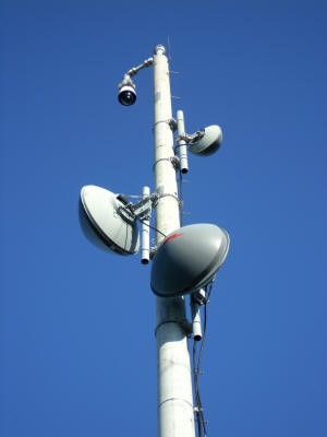
Wireless Communications generally consist of a typical configuration of wireless radio and antenna equipment, communications and power interface, lightning protection, and grounding. Also included is a cabinet/enclosure to transport information (data, voice, and video) via the backbone and/or distribution communications network between the RTMC and the ITS field devices. Installation of the wireless communications involves correct mounting and grounding of the wireless radios and antennas, accurate alignment of antennas, and proper lightening protection for all related equipment.
|  |
Equipment integration and testing is critical in the project acceptance stage of ITS facility deployment. Several stages of testing are necessary to ensure the system devices are operative before, during, and following facility installation. Subsystem testing stages include:
Factory Testing (FT) of a subsystem, such as for a DMS, is an operational test that verifies all required subsystem functions and is typically completed and approved before shipment of the device or subsystem to the project. A Bench Test (BT) is similar to the Factory Test, but it proves that the subsystem is operational. This test may include all components of a particular subsystem or a combination of subsystems, as may be required. Standalone Testing (ST) is a field site acceptance test of a particular individual subsystem, like an RDS, but may also include other subsystems that may help demonstrate that the RDS is functioning as required. Final System Acceptance Testing (FSAT) is performed from the RTMC where all subsystems are reporting data and video. These tests are typically performed utilizing the subsystem vendor software to prove system functionality. Subject to the contract requirements, and as a second step to the Systems Test, it will be required that all subsystems functions perform acceptably when controlled with the RTMC central software. The central software centralizes the control of the subsystems by eliminating the need to use multiple sets of subsystem vendor software. Most ITS projects require the contractor to prepare project-specific test plans for approval by FDOT prior to the start of any testing. The CEI must review and understand the approved test plans prior to witnessing any subsystem test.
|   |